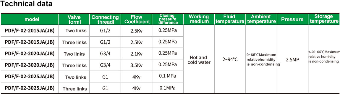
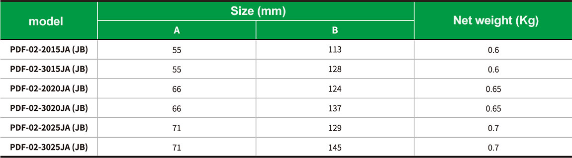
")
Electric Valve PDF/F-02-3015JA(JB)
Product introduction
The DF-02 series of switch-type electric valves consists of DF/Q-JA series valve actuators and DF/F-02 series copper valves. It is used to control the opening or closing of pipes in cold water or hot water air conditioning systems to achieve the purpose of controlling room temperature. The drive is driven by a one-way hysteresis synchronous motor with the valve spring reset. When the valve is not working, it is in the normally closed state. When it needs to work, the thermostat provides an opening signal to make the drive connect to the AC power supply, open the valve, and the cold water or hot water enters the fan coil to provide air-conditioning or heating to the room. When the room temperature reaches the set value of the thermostat, the thermostat cuts off the valve opening current, and the return spring closes the valve, thereby cutting off the water flow into the fan coil. By closing and opening the valve, the room temperature is always within the temperature set temperature range.
The drive and valve of the DF-02 series electric valve are threaded to install the drive after the valve is installed. On-site assembly, flexible wiring and convenient. The flat design of the drive can be mounted close to the wall and takes up little space. The product is reliable and durable, has low working noise, and can be reliably operated in a high temperature and high humidity environment often found in concealed fan coil units.
Operation and precautions
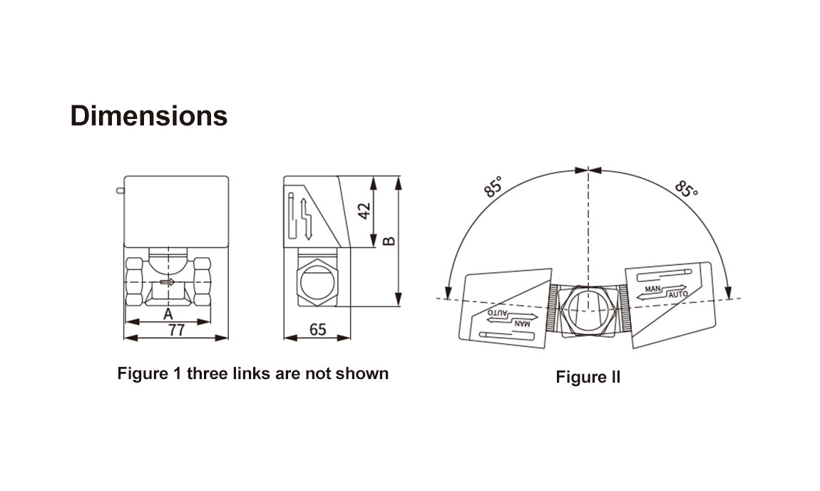
The motor housing should prevent water from seeping in. When the valve is installed in a horizontal pipe; the angle between the installation position and the plane does not exceed 85° as shown in Figure 2. When the valve is mounted on a vertical pipe, the motor casing must be protected from dripping.
When the manual lever is moved, it should move slowly. When the manual lever moves slowly along the arrow and presses into the notch, the valve is in the normally open state. When the current passes through the electric valve for the first time, the manual lever will be set to automatic again. position.
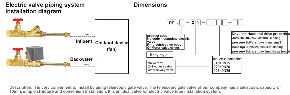
Installation instructions
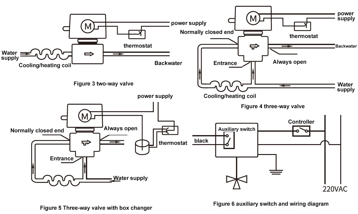
The installation of the normally closed two-way valve and the split three-way valve is shown in Figures 3, 4 and 5. For high-rise buildings, a pressure relief valve should be used on the bottom branch. When installing the valve body, be careful that the valve body arrow points. If there is an auxiliary switch, its wiring is shown in Figure 6.